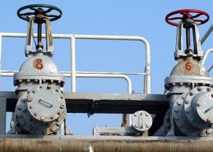
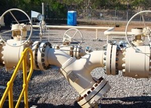
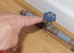
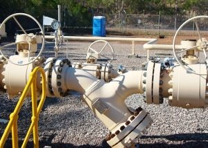
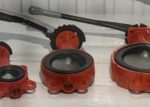
Piping of any type requires special parts, with the help of which the flow of the working medium is completely blocked or partially limited. For this, we can use the usual valves and taps for all of us. However, such valves as cast-iron valves were most widely used. Complete blocking of the movement of the medium along the highway is due to its installation at right angles to the direction of flow of the working medium.
Content
Advantages, Disadvantages and Classification
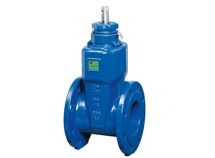
The specificity of the cast-iron gate valve device is that its locking element can only be in one of the two extreme positions - “Open” and “Closed”. That is, it is not intended for smooth regulation of the volume of the substance passing through the pipeline.
Cast iron gate valves have the following main advantages:
- suitable for use in a variety of conditions;
- have a small construction length;
- characterized by insignificant hydraulic resistance. Due to this property, a cast-iron gate valve is an integral component of any main pipeline;
- comparative simplicity of design.
Experts highlight such devices and a number of shortcomings.
- wear in the valve and valve body of the sealing surfaces, which are difficult to repair;
- considerable time is required for closing and opening reinforcement of this type;
- high construction height (this applies especially to cast-iron wedge gate valves with a sliding spindle).
These devices are classified according to three main criteria.
1. The design of the locking part. Gate valves are wedge and parallel.
2. Working pressure: high, medium, low.
Good to know! The case of the product will tell the consumer about belonging to a particular group. Cast iron valves designed for low pressure operation have a flat shape, with an average pressure level - oval, and for those capable of withstanding high pressure the body is already spherical.
3. Location of running gear: with extendable spindle, with non-extendable spindle.
Principle of operation and features
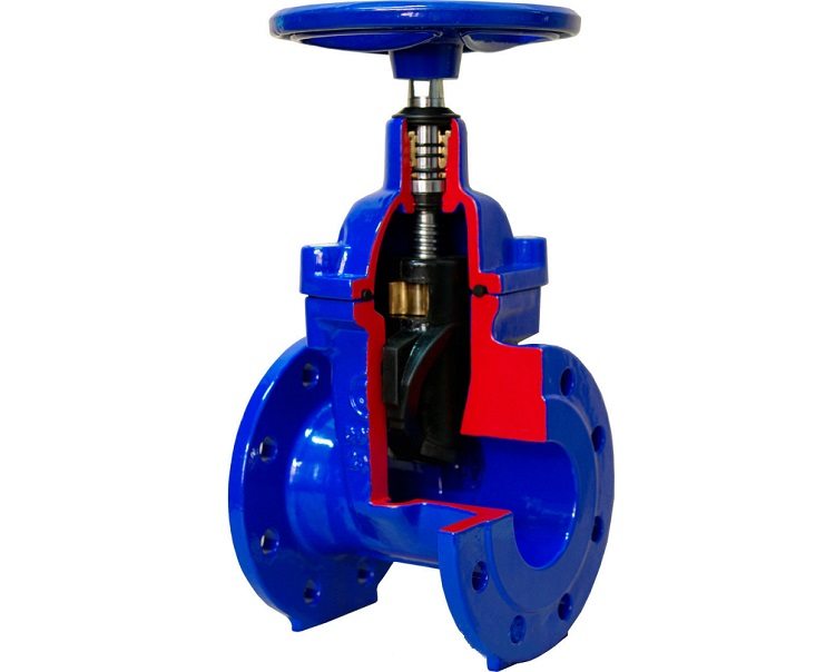
Parallel cast-iron valves block the flow due to the fact that two series-connected disks that are part of their design move apart when the wedge placed between them lowers. O-rings in the housing and on the disks are perpendicular to the valve axis.
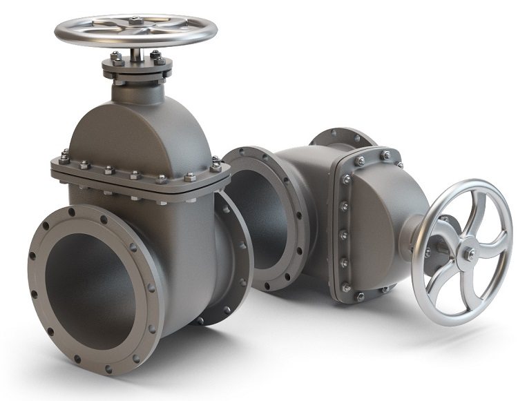
Gate valves are available in different diameters, models of the largest diameters are equipped with electric actuators.
Devices of a parallel type from cast iron are produced at a nominal pressure of about 10 bar for steam and water, the temperature of which reaches 200 ° C. The diameter of the products can be 420, 350, 200, 125, 100, 80 and 50 millimeters. Moreover, parts with diameters of 420-125 mm are also produced with an electric drive.
This design allows you to control the operation of such devices remotely. With this in mind, the installation of an electric cast iron gate valve is practiced in hard-to-reach areas of the pipeline.Overlapping the movement of the working medium in this case is performed from a single control panel and control the operation of the highway.
In addition to ease of operation, electric gate valves accelerate this process. This is often useful, especially if the pipeline has a large diameter. Therefore, valves with electric drives can often be seen in critical sections of highways. It should be noted one design feature of these parts. The electric drive can be equipped with a return spring. Such a device of the locking mechanism ultimately provides an increase in the speed of its reaction to the control signal.
Unlike parallel, closing the passage in the wedge gate valve is performed by a wedge mounted on the spindle. With rare use of this mechanism, the wedge may jam. In addition, o-rings in a wedge gate valve wear out faster than in a parallel valve. However, in a product with a rubber wedge, this disadvantage is not so noticeable. Among other features of such a technical solution, it is worth highlighting:
- the ability to withstand the movement speed of a gaseous medium up to 30 m / s, and liquid - up to 4 m / s;
- rubberized wedge-shaped disk allows opening and closing the passage with less effort;
- reduced torque combined with the smooth operation of cast-iron valves with a rubber wedge increases ease of use;
- for a rubberized surface, rubber is used whose quality meets the requirements of international standards;
- rubberized wedge provides higher strength and tightness of valves.
Furnace valve. Design features
Stop valves of this type are mounted in the exhaust duct of heating devices.
Helpful information! The shape of the furnace iron gate valve depends on the shape of the chimney channel. In other words, the casing of such valves must correspond to the geometry of the duct.
As in any other part similar in functionality, it includes the following elements:
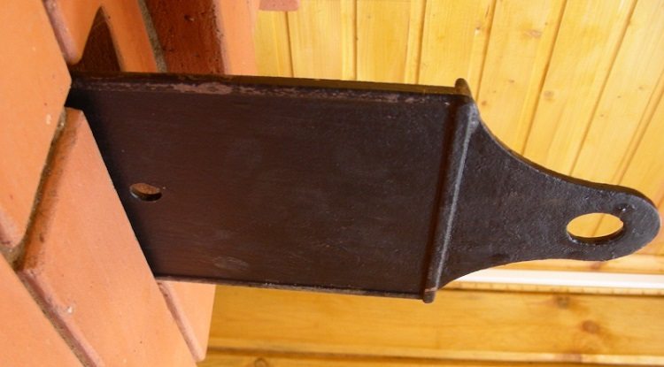
- body. It is a cast-iron frame, on the side faces of which guide grooves are located;
- locking element. This is a shield flap moving in the grooves of the body and sealing the chimney channel;
- control mechanism. It looks like an ordinary handle built into the shield flap.
The pig-iron furnace valve is produced in two versions.
Rectangular gate valve. This name does not always look correct. Indeed, her angles are 90 degrees, but today samples are produced with equal sides, that is, square.
The rectangular version can be a fairly large furnace valve with a valve length of up to 600 millimeters. The usual place of installation is the chimney channels of a Russian stove, barbecue or fireplace. AT Currently, valves with sides 26 × 13 cm are in high demand. This is exactly the size of a typical chimney of a residential building.
Round gate valve. This is a special valve, called a view. Her case looks like a rounded plate with a round hole. The locking element of such a furnace valve is a disk, which, covering the above hole, stops air exchange in the chimney. The control - the handle - is located in the center of the disk damper. Since this element is heated by the “exhaust” gases to a high temperature, it is inconvenient to regulate the air exchange with the help of the furnace gate valve. Therefore, it is usually used as an additional damper that opens before igniting the furnace. It closes after the fuel burns completely.
Installation of a pig-iron gate valve
The following methods are available for connecting shutoff valves:
- flanged;
- coupling;
- bell-shaped;
- welding.
Briefly dwell on the technology of mounting the valve flange, since such a part is most widespread.
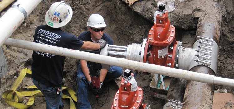
- Check compliance with trim flanges.
- Installation in the channels located on the plates, o-rings.
- Joining flanges to each other.
- Fixing them with bolts.
- Tightening the nuts.
- Joint tightness test. If necessary, the flange joint is sealed with sealant.
Cast iron stop valves for heating and water supply have recently become less commonly used. However, for the steam system, sewage and transportation of bulk materials, its role is still significant.
