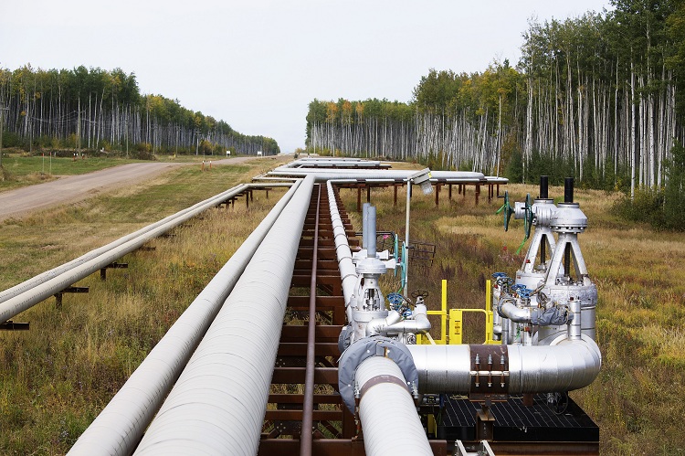
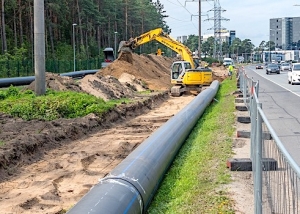
Heating mains, heating systems of buildings, hydraulic circuits of machines, drainage systems, water pipes - all these objects consist of pipelines. Engineering communications created on their basis are the most economical means of transporting various substances. Hydraulic calculation of pipelines allows you to determine the values of many characteristics at the maximum throughput of the pipe elements of the pipeline.
Content
What is calculated
This procedure is performed with respect to the following engineering communications operating parameters.
- Fluid flow rate on individual segments of the water supply.
- The flow rate of the working medium in the pipes.
- The optimum diameter of the water supply, which provides an acceptable pressure drop.
Consider the methodology for calculating these indicators in detail.
Water consumption
Data on the normative water consumption by individual plumbing fixtures are indicated in the appendix to SNiP 2.04.01-85. This document regulates the construction of sewer networks and internal water supply systems. The following is part of the relevant table.
Table 1
| Plumbing fixture | Total flow (domestic hot water and cold water), liter / second | Consumption of cold water, liter / second |
| Toilet bowl with direct water valve | 1,4 | 1,4 |
| Toilet bowl with a tank for draining water | 0,10 | 0,10 |
| Shower cubicle (mixer) | 0,12 | 0,08 |
| Bath (mixer) | 0,25 | 0,17 |
| Sink (mixer) | 0,12 | 0,08 |
| Washbasin (mixer) | 0,12 | 0,08 |
| Washbasin (water taps) | 0,10 | 0,10 |
| Watering tap | 0,3 | 0,3 |
If you intend to use several devices at the same time, the flow is added up. So, in the case when the shower is working on the first floor with the simultaneous use of the toilet on the second floor, it is logical to add the volume of water consumption by both consumers - 0.12 + 0.10 = 0.22 liter / second.
Important! The following rule applies to fire water pipelines: for one jet, it must provide a flow rate of at least 2.5 liters / sec.
It is quite clear that during fire fighting, the number of jets from one fire hydrant is determined by the area and type of building. For ease of reference, information on this issue is also available in tabular form.
table 2
| Type of building | Fire extinguishing quantity required |
| Administration of enterprises (volume up to 25,000 cubic meters) | 1 |
| Public buildings (volume up to 25,000 cubic meters, more than 10 floors) | 2 |
| Public buildings (volume up to 25,000 cubic meters, up to 10 floors) | 1 |
| Management building (volume up to 25,000 cubic meters, 10 and more floors) | 2 |
| Management building (from 6 to 10 floors) | 1 |
| Residential building (from 16 to 25 floors) | 2 |
| Residential building (up to 16 floors) | 1 |
Flow rate
Suppose that we are faced with the task of calculating a dead-end water supply network at a given peak flow rate through it. The purpose of the calculations is to determine the diameter at which an acceptable flow rate through the pipeline will be ensured (according to SNiPu - 0.7 - 1.5 m / s).
We apply the formulas. The size of the pipeline is related to the water flow rate and its flow rate by the following formulas:
S = π * R2 where
S is the cross-sectional area of the pipe.Unit of measurement - square meter; π is the known irrational number; R is the radius of the inner diameter of the pipe.
Unit of measurement - the same square meters.
On a note! For cast iron and steel pipes, the radius is usually equated to half of their nominal diameter (DN). Most plastic tubular products have a nominal outside diameter one step larger than the inside diameter. For example, for a polypropylene pipe with an internal cross section of 32 millimeters, the outer diameter is 40 millimeters.
The following formula looks like this:
W = V × S, where
W - water consumption in cubic meters; V - water flow rate (m / s); S - sectional area (square meters).
Example. We will calculate the fire extinguishing system pipeline for one jet, the water flow in which is 3.5 liters per second. In the SI system, the value of this indicator will be: 3.5 l / s = 0.0035 m3 / s. This flow rate per jet is normalized to extinguish a fire inside storage and industrial buildings with a volume of 200 to 400 cubic meters and a height of up to 50 meters.
First we take the second formula and calculate the minimum cross-sectional area. If the speed is 3 m / s., This indicator is equal to
S = W / V = 0.0035 / 3 = 0.0012 m2
Then the radius of the inner section of the pipe will be like this:
R = √S / π = 0.019 m.
Thus, the inner diameter of the pipeline should be equal to a minimum
Ext. = 2R = 0.038 m = 3.8 centimeters.
If the result of the calculations is an intermediate value between the standard values of the dimensions of the tubular products, rounding is performed upwards. That is, in this case, a standard steel pipe with DN = 40 mm is suitable.
How easy is it to find out the diameter. In order to perform a quick calculation, you can use another table that directly relates the flow of water through the pipeline to its nominal diameter. It is presented below.
Table 3
| Consumption, liter / sec. | Minimum remote control of the pipeline, millimeters |
| 10 | 50 |
| 6 | 40 |
| 4 | 32 |
| 2,4 | 25 |
| 1,2 | 20 |
| 0,6 | 15 |
| 0,20 | 10 |
Loss of pressure
The calculation of the pressure loss in a section of a pipeline of known length is quite simple. But here you need to use a fair amount of variables. You can find their values in the directories. And the formula is as follows:
P = b × L × (1 + K), where
P - pressure loss in meters of water. This characteristic is applicable in view of the fact that the pressure of water in its flow changes; b - hydraulic slope of the pipeline; L is the length of the pipeline in meters; K is a special coefficient. This setting depends on the purpose of the network.
This formula is greatly simplified. In practice, pressure drops are caused by valves and pipe bends. With the figures representing this phenomenon in the fittings, you can familiarize yourself by studying the following table.
Table 4
| Equivalent to the length of the straight section of the pipeline, meters | ||||||||||||
| Diameter | 300 | 250 | 200 | 150 | 125 | 100 | 80 | 65 | 50 | 40 | 32 | 25 |
| 50% open stopcock | 60 | 60 | 60 | 45 | 30 | 30 | 15 | 15,0 | 15 | 15,0 | 15 | 15,0 |
| 75% open stopcock | 8 | 8 | 8 | 6 | 4 | 4 | 2 | 2 | 2 | 3 | 3 | 2 |
| 100% open stopcock | 2 | 2 | 2 | 1,5 | 1 | 1 | 0,50 | 0,50 | 0,5 | 0,5 | 0,50 | 0,5 |
| Check valve | 35 | 25 | 25 | 20 | 15 | 10 | 9 | 8 | 7 | 6 | 5 | 4 |
| The folding check valve | 45 | 30 | 30 | 25 | 20 | 15 | 12 | 10 | 9 | 8 | 7 | 6 |
| Conical narrowing | 5,0 | 5,0 | 5,0 | 5,0 | 5,0 | 5,0 | 5,0 | 5,0 | 5,0 | 5,0 | 5,0 | 5,0 |
| 90 degree elbow | 7 | 5 | 4 | 2,7 | 2,5 | 1,7 | 1,30 | 0,9 | 0,70 | 0,6 | 0,40 | 0,3 |
| 90 degree bend | 5,5 | 5 | 3 | 2 | 1,8 | 1,20 | 1 | 0,7 | 0,50 | 0,4 | 0,30 | 0,2 |
Some elements of the above formula need to be commented. The odds are simple. Its values can be found in SNiPa No. 2.04.01-85.
Table 5
|
Purpose of the water supply |
Coefficient |
| Fire fighting | 0,15 |
| Household drinking | 0,3 |
| Fire fighting | 0,1 |
| Economic production and fire | 0,2 |
As for the concept of "hydraulic slope", then everything is much more complicated.
Important! This characteristic displays the resistance exerted by the pipe to the movement of water.
Hydraulic slope is a derivative of the following parameters:
- flow rate. The dependence is directly proportional, that is, the hydraulic resistance is higher, the faster the flow moves;
- pipe diameter.Here the dependence is already inversely proportional: the hydraulic resistance increases with a decrease in the cross section of the engineering branch;
- roughness of the walls. This indicator in turn depends on the material of the pipe (the surface of the HDPE or polypropylene is smoother than that of steel). In some cases, an important factor is the age of the water pipes. Lime deposits and rust formed over time increase the surface roughness of their walls.
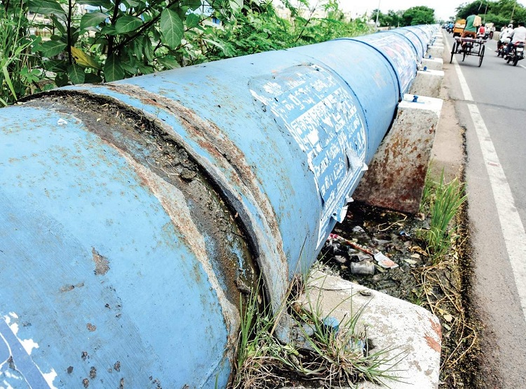
In old pipes, the hydraulic resistance increases, since due to overgrowing of the inner walls of the pipes, their clearance is narrowed
Using the Shevelev table
To solve the problem associated with determining the hydraulic slope using a calculator, you can completely using the table of hydraulic calculation of water pipes developed by Shevelev F.A. It contains data for different diameters, materials and flow rates. In addition, the table contains amendments relating to old pipes. But here one point should be clarified: age corrections do not apply to all types of polymer pipe products. The surface structure of ordinary or cross-linked polyethylene, polypropylene and metal plastic does not change during the entire period of operation.
Due to the large volume of the Shevelev table, it is not practical to publish it completely. Below is just a small excerpt from this document for a plastic pipe with a diameter of 16 millimeters.
Table 6
| Speed, m / s | Flow rate liter / sec | Hydraulic slope for a pipeline length of 1000 meters (1000i) |
| 1,50 | 0,17 | 319,8 |
| 1,41 | 0,16 | 287,2 |
| 1,33 | 0,15 | 256,1 |
| 1,24 | 0,14 | 226,6 |
| 1,15 | 0,13 | 198,7 |
| 0,88 | 0,1 | 124,7 |
| 0,90 | 0,09 | 103,5 |
| 0,71 | 0,08 | 84 |
When analyzing the results of calculating the pressure drop, it must be borne in mind that most of the plumbing fixtures require a certain amount of overpressure for normal operation. The SNiP, adopted 30 years ago, provides figures for already obsolete equipment. More modern models of household and sanitary equipment require for normal operation that the overpressure is at least 0.3 kgf / cm2 (or 3 meters of pressure). However, as practice shows, it is better to put in the calculation a slightly larger value of this parameter - 0.5 kgf / cm2.
Examples
For better assimilation of information below is an example of a hydraulic calculation of a plastic water supply. The following data are accepted as initial data:
- diameter - 16.6 mm;
- length - 27 meters;
- the maximum permissible water flow rate is 1.5 m / s.
On a note! When the water supply system is commissioned, tests are carried out with a pressure equal to at least the worker multiplied by a factor of 1.3. In this case, the act of hydraulic testing of a particular branch of the pipeline should include marks on the test pressure, as well as on the duration of the test work.
The hydraulic slope of a length of 1000 meters is (we take the value from the table) 319.8. But since the formula for calculating the pressure drop must not be substituted for 1000i, but simply i, this indicator must be divided by 1000. As a result, we get:
319,8:1000=0,3198
For domestic drinking water supply, the coefficient K is taken equal to 0.3.
After substituting these values, the formula will look like this:
P = 0.3198 × 27 × (1 + 0.3) = 11.224 meters.
Thus, an overpressure equal to 0.5 atmosphere will be produced at the end plumbing fixture at a pressure in the pipeline of the water supply system of 0.5 + 1.122 = 1.622 kgf / cm2. And since the pressure in the line, as a rule, does not fall below 2.5 - 3 atmospheres, this condition is quite feasible.
Hydraulic calculation of pipelines of heating systems using programs
Calculation of heating a private house is a rather complicated procedure. However, special programs greatly simplify it. Today, a selection of several online services of this type is available. The output contains the following data:
- required diameter of the pipeline;
- a certain valve used for balancing;
- sizes of heating elements;
- differential pressure sensors values;
- control parameters for thermostatic valves;
- numerical settings of regulatory parts.
Oventrop co program for the selection of polypropylene pipes. Before starting it, you must determine the required items of equipment and set the settings. At the end of the calculations, the user receives several options for implementing the heating system. They iteratively make changes.
This hydraulic calculation software allows you to select pipe elements of the line of the desired diameter and determine the flow rate of the coolant. It is a reliable assistant in the calculation of both single-pipe and two-pipe structures. Convenience of work is one of the main advantages of Oventrop co. This program includes ready-made blocks and catalogs of materials.
HERZ CO program: calculation taking into account the collector. This software is freely available. It allows you to make calculations regardless of the number of pipes. HERZ CO helps to create projects for renovated and new buildings.
Note! There is one caveat: glycol mixture is used to create structures.
The program also focuses on the calculation of one- and two-pipe heating systems. With its help, the action of the thermostatic valve is taken into account, and pressure losses in heating devices and an indicator of resistance to flow of the heat carrier are also determined.
The calculation results are displayed in graphical and schematic form. HERZ CO has a help function. The program has a module that performs the function of searching and localizing errors. The software package will contain a catalog of data on appliances for heating and valves.
Instal-Therm HCR software product. Using this software, radiators and surface heating can be calculated. Its delivery kit includes the Tece module, which contains routines for designing various types of water supply systems, scanning drawings and calculating heat losses. The program is equipped with various catalogs that contain fittings, batteries, thermal insulation and a variety of fittings.
Computer program "TRANSIT". This software package allows multivariate hydraulic calculation of oil pipelines in which there are intermediate oil pumping stations (hereinafter NPS). The initial data are:
- absolute roughness of pipes, pressure at the end of the line and its length;
- elasticity and kinematic viscosity of saturated vapors of oil and its density;
- make and number of pumps included both at the head station and at intermediate pump stations;
- pipe layout by diameter;
- pipeline profile.
The calculation result is presented in the form of data on the characteristics of gravity sections of the trunk and on the pumping rate. In addition, the user is given a table showing the pressure value before and after any of the NPS.
In conclusion, it must be said that the simplest calculation methods were given above. Professionals use much more complex schemes.
