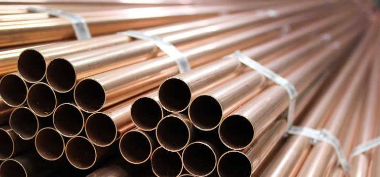
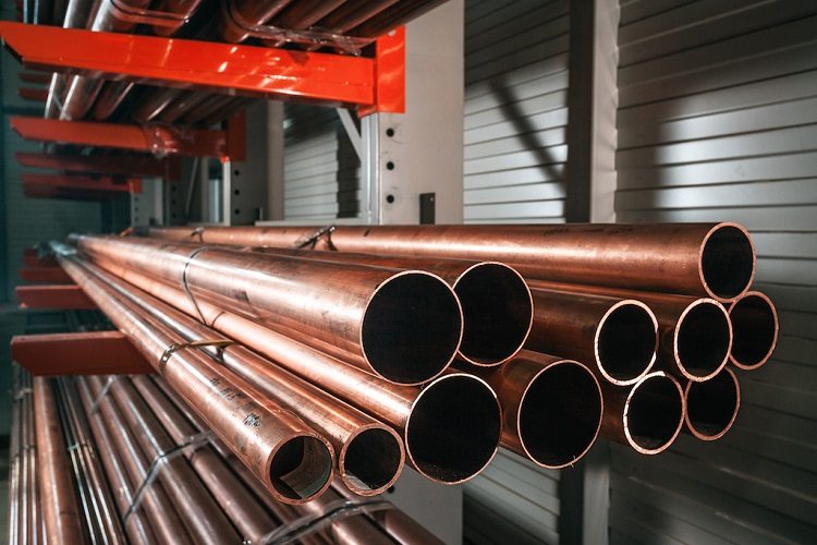
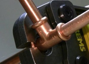
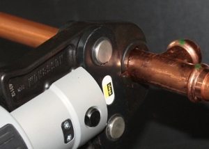
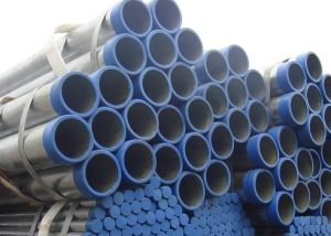
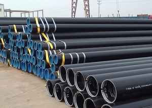
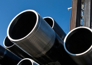
Standards 11383 of ´75 and 617 of 2006 are normative documents that apply to brass and copper pipes. At the same time, GOST 11383 concerns round drawn thin-walled tubes used in various industries, and 617-2006 - round cold-formed and pressed general-purpose products. The documents establish the requirements, acceptance conditions, assortment, test methods, control, storage, labeling and transportation of pipes.
Content
- 1 Copper tube application
- 2 Communication production methods
- 3 Assortment of thin-walled copper products
- 4 Maximum deviations of diameters according to document 617-2006
- 5 Permissible dimensions of thin-walled pipes
- 6 Extreme deviations of wall thickness
- 7 Standardization of copper pipe length
- 8 Symbol of copper tubes
- 9 Some characteristics of copper tubes
- 10 The chemical composition of copper for pipes according to GOST 617
- 11 Basic mechanical properties of products
- 12 Pipe surface requirements
- 13 Kosina cut and ovality according to GOST
- 14 Pipe acceptance according to document 11383-75
- 15 Test Methods Used
Copper tube application
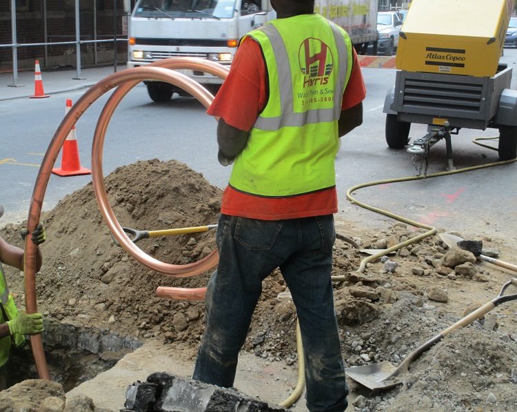
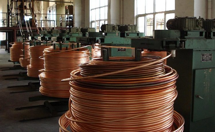
Copper communications are a fairly common solution for arranging systems for various purposes. Due to their properties, they can be used as a gas pipeline, fuel pipeline, water supply system, as well as in heating systems and industry.
Copper products are used as water supply elements for various purposes based on the duration of the service life, chemical inertness to such a substance as chlorine, bactericidal properties and corrosion resistance. At the same time, installation is possible both for a single consumer and for multi-storey buildings.
For heating systems, copper pipes are good due to their ability to withstand pressure surges and temperatures up to 250 degrees. Such characteristics are explained by the high plasticity of communications. When used in warm floors, copper elements do not wear out.
The use of copper fuel pipelines is possible due to the high tightness of the installed system. The same property allows you to route gas pipelines, for example, in apartments.
In addition, copper tubes are included in the design of various hydraulic and brake systems, heat exchangers, airplanes and trucks, climate circuits, etc.
Communication production methods
GOST defines 2 technological operations for obtaining a copper pipe:
- rental;
- pressing (subsequent welding of joints is assumed).
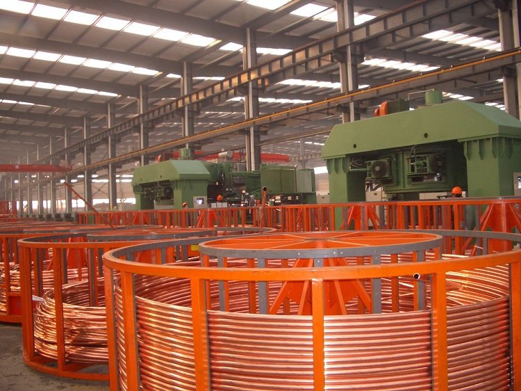
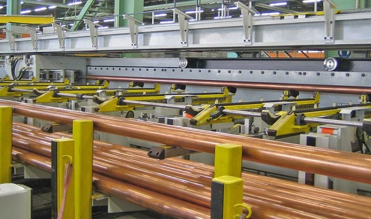
Both methods are suitable for the production of round pipes. Products with a square cross section are mainly made by pressing. Rolled pipes require the use of cold deformation. Without preheating, ductile metal - copper - can be rolled between two rollers. A blank - a sleeve, is simply put on the rolling mill. It rolls out to the required diameter.
At the stage of final processing, communications are divided into unannealed pipes and annealed products. The first type is stronger than heat-treated analogues, since during rolling the material was compacted by deformation of the crystal lattice.
Pressed products are made of copper in sheets on special machines.A cut-off blank is cut from each sheet, which is fed to the molding press rollers. After giving the necessary shape, the docking seam is welded.
Note! This process assumes the presence of an inert gas medium.
At the last stage, the welded pipe is passed through the calibration rollers, which align the product profile, and also correct the longitudinal deformation.
Assortment of thin-walled copper products
The copper tubes of document 11383-75 must have the dimensions shown in the table.
Table 1
| Diameter, * 10 mm | Maximum deviation of diameter, * 10-1 mm | Linear density (theoretical), g / m, with a wall, * 10-2 mm | |||||
| Normal accuracy | Increased accuracy | 15 | 25 | 20 | 30 | 45 | |
| 0,15 | ±1,0 | ±0,5 | 5,659 | — | — | — | — |
| 0,16 | 6,079 | — | 7,823 | — | — | ||
| 0,17 | — | — | 8,384 | — | — | ||
| 0,18 | — | — | — | — | — | ||
| 0,20 | 7,756 | 12,229 | 10,062 | 14,254 | 19,491 | ||
| 0,22 | 8,595 | 13,623 | 11,178 | — | — | ||
| 0,24 | 9,433 | 15,020 | 12,295 | — | — | ||
| 0,25 | — | 15,718 | 12,854 | — | — | ||
| 0,26 | — | 16,700 | 13,412 | — | — | ||
| 0,28 | — | 17,818 | — | — | — | ||
| 0,30 | 11,948 | 19,215 | 15,646 | 22,633 | 32,067 | ||
| 0,32 | — | — | 16,766 | — | — | ||
| 0,34 | — | — | 17,889 | — | — | ||
| 0,35 | — | 22,685 | — | — | — | ||
| 0,36 | — | 23,407 | — | — | — | ||
| 0,38 | — | — | — | — | — | ||
| 0,40 | 16,144 | 26,202 | 21,235 | 31,016 | 44,642 | ||
| 0,45 | — | 29,690 | — | — | — | ||
| 0,48 | — | — | — | 37,724 | — | ||
| 0,50 | 20,333 | 33,188 | 26,825 | 39,400 | 57,218 | ||
| 0,55 | — | — | — | — | — | ||
| 0,60 | 24,526 | 40,175 | 32,414 | 47,784 | 69,794 | ||
| 0,70 | 28,718 | 45,897 | 38,003 | 56,168 | 82,370 | ||
| 0,75 | 30,814 | — | — | — | — | ||
| 0,80 | -1,5 | -1,0 | 32,911 | 54,139 | 43,602 | 64,564 | 94,945 |
| 0,85 | — | — | — | 68,757 | — | ||
| 0,90 | 37,095 | 61,134 | 49,181 | 72,936 | 107,521 | ||
| 0,95 | — | 64,623 | — | — | — | ||
| 1,00 | 41,287 | 68,121 | 54,771 | 81,319 | 120,097 | ||
| 1,02 | — | — | — | — | — | ||
| 1,10 | -2,0 | -1,5 | 45,479 | 75,107 | 60,360 | 89,703 | 132,672 |
| 1,20 | 49,671 | 82,089 | 60,949 | 98,087 | 145,248 | ||
| 1,30 | — | 89,080 | — | 106,471 | 158,180 | ||
| 1,40 | — | — | — | 114,855 | 170,399 | ||
| 1,50 | — | 96,067 | — | 123,238 | 182,975 | ||
| 1,60 | — | — | — | 131,622 | 195,551 | ||
| 1,70 | — | — | — | — | — | ||
| 1,80 | — | — | — | — | — | ||
| 1,90 | -2,4 | -2,0 | — | — | — | — | — |
| 2,00 | — | — | — | — | — | ||
| 2,10 | — | — | — | — | — | ||
| 2,20 | — | — | — | — | — | ||
| 2,40 | — | — | — | — | — | ||
| 2,80 | — | — | — | 232,228 | — | ||
Continuation of table 1
| Diameter, * 10 mm | Maximum deviation of diameter, * 10-3 mm | Linear density (theoretical), g / m, with a wall, * 10-2 mm | ||||||
| Normal accuracy | Increased accuracy | 35 | 50 | 40 | 65 | 70 | 60 | |
| 0,15 | ±100 | ±50 | — | — | — | — | — | — |
| 0,16 | — | — | 13,414 | — | — | — | ||
| 0,17 | — | — | 14,532 | — | — | — | ||
| 0,18 | — | — | — | — | — | — | ||
| 0,20 | 16,136 | 17,889 | — | — | — | |||
| 0,22 | — | — | — | — | — | — | ||
| 0,24 | — | — | — | — | — | — | ||
| 0,25 | 21,031 | 27,946 | 24,175 | — | — | — | ||
| 0,26 | — | 29,343 | 25,362 | — | — | — | ||
| 0,28 | — | — | — | — | — | — | ||
| 0,30 | 25,917 | 34,932 | 29,067 | — | — | 40,242 | ||
| 0,32 | — | — | — | — | — | — | ||
| 0,34 | — | — | — | — | — | 46,956 | ||
| 0,35 | — | — | — | — | — | — | ||
| 0,36 | — | — | — | — | — | — | ||
| 0,38 | — | — | — | — | 60,651 | — | ||
| 0,40 | 35,801 | 48,906 | 40,248 | 60,847 | — | 57,018 | ||
| 0,45 | — | — | — | — | — | — | ||
| 0,48 | — | — | 49,181 | — | — | — | ||
| 0,50 | 45,479 | 62,878 | 51,424 | — | — | 73,777 | ||
| 0,55 | — | — | — | — | — | — | ||
| 0,60 | 55,260 | 76,852 | 63,603 | — | — | 90,545 | ||
| 0,70 | 65,041 | 90,824 | 73,781 | — | — | — | ||
| 0,75 | — | — | — | — | — | — | ||
| 0,80 | -150 | -100 | 74,822 | 104,798 | 84,959 | — | — | 123,079 |
| 0,85 | — | — | — | — | — | — | ||
| 0,90 | 84,603 | 118,770 | 96,138 | — | — | — | ||
| 0,95 | — | — | — | — | — | — | ||
| 1,00 | 94,384 | 132,744 | 107,316 | — | — | 157,615 | ||
| 1,02 | — | — | 109,548 | — | — | — | ||
| 1,10 | -200 | -150 | 104,166 | 146,716 | 118,495 | — | — | — |
| 1,20 | 113,947 | 160,690 | 129,673 | — | — | — | ||
| 1,30 | 123,728 | 174,662 | 140,851 | — | — | — | ||
| 1,40 | 133,509 | 188,636 | 152,030 | — | — | — | ||
| 1,50 | — | 202,608 | 163,208 | — | — | — | ||
| 1,60 | — | 216,582 | 174,587 | — | — | — | ||
| 1,70 | — | 230,554 | — | — | — | — | ||
| 1,80 | — | 244,528 | — | — | — | — | ||
| 1,90 | -240 | -200 | — | 258,501 | — | — | — | — |
| 2,00 | — | 272,474 | — | — | — | — | ||
| 2,10 | — | 286,447 | — | — | — | — | ||
| 2,20 | — | 300,420 | — | — | — | — | ||
| 2,40 | — | 328,366 | — | — | — | — | ||
| 2,80 | — | 284,258 | — | — | — | — | ||
Maximum deviations of diameters according to document 617-2006
Copper pipes (GOST 617) can be made with different diameters, lengths and wall thickness.
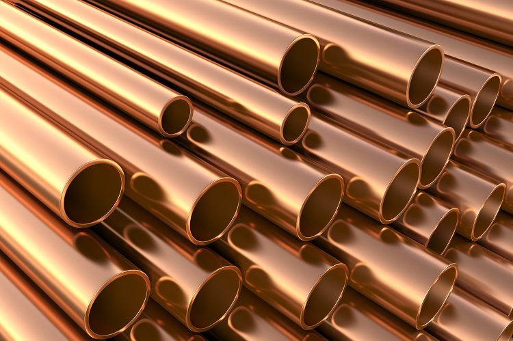
Like other types of pipes, copper products come in different diameters and with different wall thicknesses.
The permissible nominal external dimension of a cold-deformed pipe and its maximum deviations are given in the table.
table 2
| Outer diameter * 103 mm | Maximum deviation, * 10-2 mm |
| 0,003 – 0,01 | — 15 |
| 0,01 – 0,018 | — 20 |
| 0,018 – 0,03 | — 24 |
| 0,03 – 0,048 | — 30 |
| 0,048 – 0,076 | — 40 |
| 0,076 – 0,1 | — 50 |
| 0,1 – 0,12 | ± 30 |
| 0,12 – 0,139 | ± 40 |
| 0,139 – 0,17 | ± 50 |
| 0,17 – 0,235 | ± 70 |
| 0,235 – 0,36 | ± 90 |
Having agreed with the consumer, it is possible to manufacture a pipe (cold-deformed) with a deviation in the average diametric size. The corresponding values according to GOST 617 are given in the table.
Table 3
| Outer diameter * 103 mm | Ovality of the pipe, * 10-2 mm | Deviation in diameter, * 10-1 mm |
| 0,003 – 0,01 | 12 | ±0,6 |
| 0,01 – 0,02 | 16 | ±0,8 |
| 0,02 – 0,03 | 24 | ±1,2 |
| 0,03 – 0,05 | 30 | ±1,5 |
| 0,05 – 0,10 | 50 | ±2,0 |
| 0,10 – 0,20 | 100 | ±5,0 |
| 0,20 – 0,30 | 150 | ±7,5 |
| 0,30 – 0,36 | 200 | ±10 |
Pressed pipes should not go beyond the limit of deviations in diameter (according to GOST 617) given in the table.
Table 4
| Outer diameter * 103 mm | Deviation, * 10-1 mm |
| 0,03-0,036 | ±3,5 |
| 0,036-0,045 | ±4 |
| 0,045-0,050 | ±5 |
| 0,050-0,060 | ±6 |
| 0,060-0,070 | ±7 |
| 0,070-0,080 | ±8 |
| 0,080-0,090 | ±9 |
| 0,090-0,105 | ±10 |
| 0,105-0,110 | ±11 |
| 0,110-0,120 | ±12 |
| 0,120-0,130 | ±13 |
| 0,130-0,140 | ±14 |
| 0,140-0,150 | ±15 |
| 0,150-0,160 | ±16 |
| 0,160-0,170 | ±17 |
| 0,170-0,180 | ±18 |
| 0,180-0,190 | ±19 |
| 0,190-0,200 | ±20 |
| 0,200-0,220 | ±22 |
| 0,220-0,250 | ±25 |
| 0,250-0,280 | ±28 |
Permissible dimensions of thin-walled pipes
Standard 11383 defines tolerances for wall thickness (thin-walled drawn pipes) depending on the accuracy of the manufacture. The corresponding values are given in the table.
Table 5
| Wall, * 10-3 mm | Deviation, * 10-3 mm | |
| Increased accuracy | Normal accuracy | |
| 150 | ±20 | ±30 |
| 200 | ||
| 250 | ±30 | ±40 |
| 300 | ||
| 350 | ||
| 400 | ±40 | ±50 |
| 450 | ||
| 500 | ±50 | ±60 |
| 600 | ±60 | ±80 |
| 650 | ±80 | ±100 |
| 700 | ||
Thin-walled tubes (standard 11383-75) can be produced in segments from one to three meters. It is possible to have products from half a meter to 1 meter, but their number should not exceed 10% of the mass of the entire batch.
If the outer diameter is less than 1 centimeter, then manufacture in bays is permissible. The restriction on their length is 10 meters. The upper limit of the length of a pipe segment of more than 3 meters is 4.5 m. Deviation along the length of the measured product is up to +10 mm.
Document 11383-75 also defines the curvature of solid tubes. The required values are given in the table.
Table 6
| Wall, * 10-1 mm | Diameter, * 10-1 mm | Curvature value per 1 m, mm, not more |
| 1,5-2,5 | 15-60 | 5 |
| More than 3.0 | 15-60 | 8 |
| All sizes | More than 60 | 10 |
According to customer requirements, the curvature of the tubes may be less than 3 millimeters.
Extreme deviations of wall thickness
GOST 617 defines wall thicknesses and their deviations for a cold-deformed tube. The corresponding values are given in the table.
Table 7
| Wall thickness * 10-1 mm | Nominal Outer Size * 10-1 mm | Maximum deviation, * 10-2 mm | |
| Normal accuracy | High accuracy | ||
| 8 | 30-160 | ±8 | ±7 |
| 10 | 40-600 | ±10 | ±9 |
| 12 | 50-420 | ±12 | ±11 |
| 15 | 60-1000 | ±15 | ±13 |
| 20 | 60-1000 | ±20 | ±18 |
| 25 | 90-1650 | ±25 | ±20 |
| 30 | 110-2310 | ±25 | ±24 |
| 35 | 150-3570 | ±30 | ±25 |
| 40 | 160-3580 | ±30 | ±28 |
| 45 | 230-900 | ±35 | ±32 |
| 50 | 200-3600 | ±40 | ±35 |
| 60 | 220-2120 | ±50 | ±42 |
| 70 | 240-3500 | ±60 | ±49 |
| 80 | 800-3500 | ±60 | ±56 |
| 100 | 340-3150 | ±75 | — |
It is acceptable to make copper tubes with intermediate wall thickness indicators. In this case, the limit deviations are selected based on the nearest value.
Note! Having agreed with the consumer, it is possible to produce copper products for which deviations are expressed as a percentage of the total thickness.
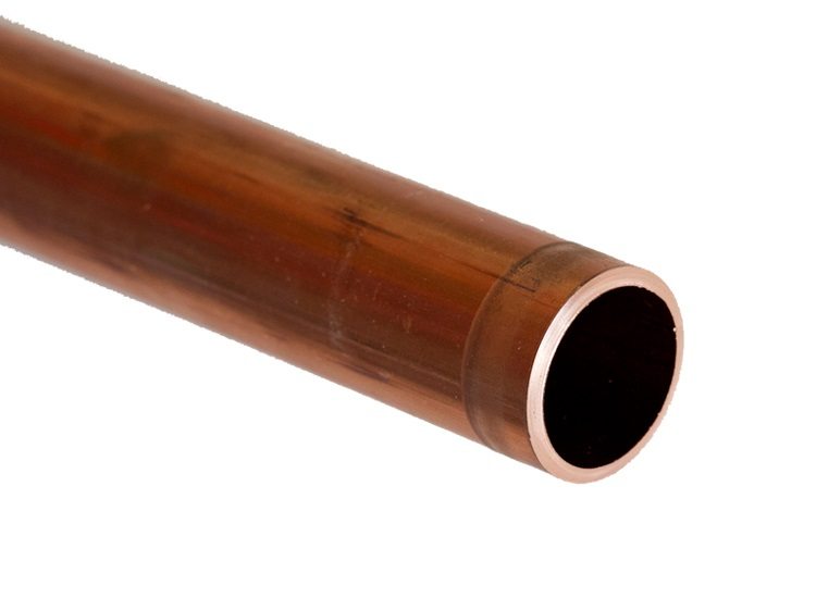
The wall thickness of the pipe is also regulated by GOST, but in agreement with the customer, products of non-standard sizes can be produced
For cold-deformed pipes, the corresponding parameters according to GOST 617 are given in the table.
Table 8
| Outer size * 10-1 mm | Deviation, * 10-1, % | |||
| from the wall 0.8-1 mm | from the wall 1-3 mm | from the wall 3-6 mm | from the wall 6-10 mm | |
| 30-400 | ±150 | ±130 | ±110 | ±100 |
| 400-1200 | ±150 | ±130 | ±120 | ±110 |
| 1200-2500 | — | ±130 | ±130 | ±120 |
| 2500-3600 | — | — | ±150 | ±150 |
According to GOST, pressed copper pipes must have walls with the maximum deviations indicated in the table.
Table 9
| Wall, * 10-1 mm | Outer diameter mm | Deviation of wall thickness, * 10-1 mm |
| 50 | 30-70 | ±5 |
| 60 | 32 to 42 | ±6 |
| 70 | 36 to 44 | ±7 |
| 75 | 40-90 | ±7,5 |
| 80 | 42 to 46 | ±8 |
| 85 | 40 | ±8,5 |
| 100 | 34-280 | ±10 |
| 125 | 50-195 | ±12 |
| 150 | 50-270 | ±14 |
| 175 | 75-195 | ±16 |
| 200 | 80-280 | ±18 |
| 225 | 85-195 | ±18 |
| 250 | 90-270 | ±20 |
| 275 | 95-195 | ±22 |
| 300 | 100-280 | ±24 |
Standardization of copper pipe length
GOST 617-2006 standardizes the lengths of copper pipes. Products can be produced in bays or segments. In the second case, the manufacture of pipes of unmeasured, as well as measured (or multiple measured) lengths is allowed. So, the length of cold-deformed products can be in the range of 15-60 (* 10-1 m), pressed - 10-60 (* 10-1 m).
For pipes of a length that is a multiple of measured, it is necessary to allow half a centimeter for each cut, and deviations of the total length are set as for products of measured length.
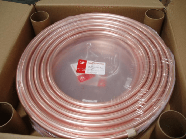
Pipes in coils are supplied with a length of not less than 10 meters with an outer diameter of up to 1.8 cm. Having agreed with the consumer, drawn products can be made in coils of the following types:
- BT - free winding bay.
- BU - a bay of ordered layered winding.
- BS - spiral flat winding bay.
For products of measured length, the limit deviations must correspond to the values in the table.
Table 10
| Diameter, * 10-1 mm | Deviation of length, * 10-1 mm | |
| <2000 | ≥2000 | |
| 30-500 | +60 | +100 |
| 500-1500 | +100 | +150 |
| >1500 | +180 | +240 |
Similar parameters, if there is increased manufacturing accuracy, are given in the table.
Table 11
| Diameter, * 10-1 mm | Deviation of length, * 10 mm | |
| 1000-4000 | >4000 | |
| 30-250 | +0,5 | Values are agreed with the consumer. |
| 250-1000 | +0,7 | |
| >1000 | +1,0 | |
Symbol of copper tubes
GOST 617-2006 and 11383-75 establish a general scheme for product symbolization. Its composition by documents is shown in the table.
Table 12
| Parameter | By 617-2006 | Po 11383-75 |
| Preparation method | G - pressed
D - cold deformed (cold rolled or drawn) |
D - drawn |
| Sectional shape | KR - Round | |
| Manufacturing accuracy | And - normal (on the wall) and increased (in diameter)
N - normal (in diameter and wall) P - increased (in diameter and wall) K - increased (along the wall) and normal in diameter Y - in% of wall thickness C - normal (average diameter) |
H is normal and
P - increased |
| condition | M - soft
L - soft with increased ductility P - semi-solid F - semi-solid with increased strength T - solid H - solid with increased strength |
M - soft
T - solid |
| Dimensions | Diameter and Wall | |
| Length | ND - unmeasured
CD - multiple dimensional |
CD - multiple
ND - unmeasured MD - measured BT - in the bays |
| Metal grade | — | |
| Special conditions | B - pipes with increased accuracy along the length
O - pipes with increased accuracy along the length P - Regulatory requirements for tensile tests N - regulated requirements for Vickers hardness measurements |
L - increased ductility
G - pressed billet C - welded billet P - any workpiece |
| Standard designation | Name GOST | |
Some characteristics of copper tubes
Unlike steel pipes, copper pipes are not afraid of freezing water inside the system. Due to their plasticity they can expand. After defrosting, the walls of the products do not crack and are able to function effectively again.
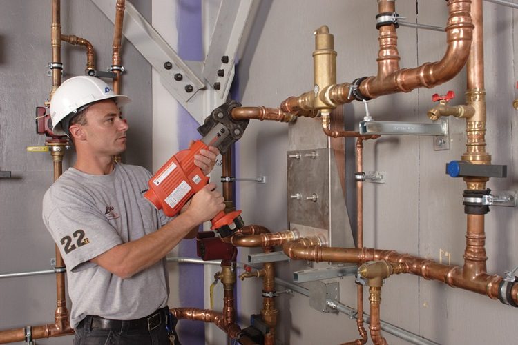
Copper pipes are able to withstand high pressure, high temperature and do not fail with a difference in these indicators
The roughness of a copper tube is 100 times lower than steel, and 5 times lower than plastic. Thus, high throughput of the pipeline is ensured when using communications of smaller diameters.
Note! If the temperature of the liquid medium is 100 ºС, then the copper water supply can withstand a pressure of 2.2-23 (* 10) atmospheres.
The use of a copper pipe in the shell will protect the network from the influence of stray currents, as well as reduce heat loss. Thanks to the protective coating, condensation is not possible on the product.The insulation may be a polyethylene layer, a coating of foamed polyurethane and other polymeric forms.
The chemical composition of copper for pipes according to GOST 617
GOST 617 determines the content of impurities in copper for the manufacture of pipes for grades: M3r, M1, M1f, M2, M1r, M3 and M2r.
Table 13
| Element | Mass fraction of component for grades, * 10-3 % | ||||||
| M1 | M3 | M1r | M2 | M1f | M3r | M2p | |
| Copper and silver | 99,9 | 99,5 | 99,9 | 99,7 | 99,9 | 99,5 | 99,7 |
| Bismuth | 1 | 3 | 10 | 2 | 10 | 3 | 2 |
| Iron | 5 | 50 | 50 | 50 | 50 | 20 | 50 |
| Nickel | 2 | 200 | 20 | 200 | 20 | 200 | 200 |
| Zinc | 4 | — | 50 | — | 50 | — | — |
| Tin | 2 | 50 | 20 | 50 | 20 | 50 | 50 |
| Antimony | 2 | 10 | 20 | 5 | 20 | 50 | 5 |
| Arsenic | 2 | 50 | 20 | 10 | 20 | 50 | 10 |
| Lead | 5 | 50 | 50 | 10 | 50 | 30 | 10 |
| Sulfur | 4 | 10 | 50 | 10 | 50 | 10 | 10 |
| Oxygen | 50 | 80 | 100 | 70 | — | 10 | 10 |
| Phosphorus | — | — | 2 to 12 | — | 12 to 40 | 5 to 60 | 5 to 60 |
Basic mechanical properties of products
Regulatory documents for copper products determine the mechanical properties that the finished product must possess.
The relevant indicators according to GOST 617 are given in the table (legend: P - tensile, P - strength determination, linear dimensions in millimeters).
Table 14
| Coldly-
deformed pipes |
Extruded pipes | |||||||||
| Material condition | Soft | Half-
hard |
Solid | — | ||||||
| Type of test | R | P | R | R | P | R | P | R | ||
| Diameter | Min. * 10-1 | 30 | 100 | 30 | 30 | 100 | — | — | 2000 | |
| Max. | 360 | 360 | 360 | 360 | 360 | 200 | 200 | — | ||
| Wall | Min. * 10-1 | 8 | 10 | 8 | 8 | 10 | 50 | 50 | 50 | |
| Max. | 10 | 10 | 10 | 10 | 10 | 30 | 30 | 30 | ||
| Temporary resistance, *103 kPa |
Min | 200 | — | 240 | 280 | — | 190 | — | 180 | |
| After the gap relative extension, % |
Min | On the short samples |
38 | — | 10 | — | — | 32 | — | 32 |
| Min | On the long samples |
35 | — | 8 | — | — | 30 | — | 30 | |
| Hardness according to vickers |
Min | — | — | — | — | 90 | — | — | — | |
| Max. | — | 55 | — | — | 135 | — | 80 | — | ||
Having agreed with the consumer, it is possible to produce pipes in a soft state with increased ductility, and solid and semi-solid pipes with increased strength.
For such cold-deformed products, the mechanical properties should correspond to the table.
Table 15
| Material condition | Test type | Temporary resistance, * 10, MPa |
After the break relative elongation,% |
| Min | Min | ||
| Soft | Tensile | 21,0 | 40 |
| Semi-solid | 27,0 | 8 | |
| Solid | 31,0 | — |
Pipe surface requirements
GOST 617, like document 11383-75, defines the basic requirements for the surface of products. There should be no dirt inside or outside the pipe that makes it difficult to inspect.
Note! According to the standard 11383-75, the presence of shells, cracks or delaminations on the surface of the finished product is strictly unacceptable.
Slight minor surface defects are possible, dents no more than a quarter of a millimeter, the number of which is no more than 2 per meter of length, if they do not bring the total size beyond the limit deviations (GOST 11383 from ´75 years). Moreover, no more than 10% of products with such defects are allowed in a batch.
If solid copper tubes (document 11383) are manufactured with increased accuracy, then local dents can have a depth of not more than 0.2 mm and the number of such products cannot exceed 2% of the entire batch. The presence of ringing, discoloration, oxidation, local browning is acceptable, which does not impede the visual inspection.
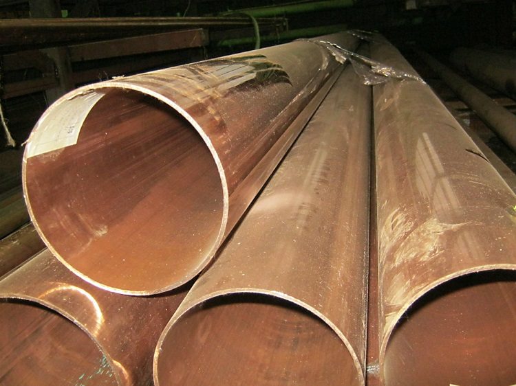
When checking the quality of pipes, not only their mechanical properties are evaluated, but also their appearance
Kosina cut and ovality according to GOST
Thin-walled copper tubes (11383-75) should be evenly cut and free of burrs. The standard normalizes the cut cosine, which for products with a diameter of up to one centimeter is not more than one millimeter, and for large pipes - two millimeters. If the products are delivered in bays, then there are no restrictions on this parameter.
The unevenness of the wall thickness should not go beyond the limit deviations (GOST 11383). If this value is less than 1/20 of the outer diameter, the required ovality is less than 0.5 mm (0.25 mm for products with high accuracy). By agreement with consumers, this figure may be increased.
GOST 617 defines the values of the cut cosine, which are presented in the table.
Table 17
| Diameter, * 104 mm | Kosina, not more than, mm |
| up to 0.002 | 2 |
| 0,002-0,005 | 3 |
| 0,005-0,01 | 4 |
| 0,01-0,017 | 5 |
| more than 0.017 | 7 |
This standard does not establish ovality:
- for pipes in bays;
- pressed with a wall of less than 1/15 of the outer size;
- cold-deformed in solid and semi-solid states with a wall of less than 1/30 of the external size;
- cold-deformed products in a soft state.
GOST 617 also permits the production of pipes in coils where the ends are chopped off.
Pipe acceptance according to document 11383-75
According to GOST, products are accepted in batches. Each of them should not exceed 500 kg in weight.
A batch may include tubes of the same size, grade of alloy or metal, state of the material and manufacturing accuracy. The accompanying document shall indicate:
- the size;
- trademark;
- grade of alloy or metal;
- used manufacturing method;
- material condition;
- batch number;
- batch net weight;
- standard.
At the request of the consumer, the accompanying quality document may also contain test results. Inspection of the outer surface is performed for each pipe of the batch, the inner - 3 products having a diameter of more than 3 mm, from every hundred kilograms. If the internal size is less than 3 mm, then such a check is not performed.
Note! Tests for tightness and flattening of tubes from welded billets are subjected to 3 products from the party. 2 tubes from a batch are subject to the chemical analysis.
If the results obtained are unsatisfactory in at least 1 of the required indicators, then repeated tests are necessary. They should be carried out on twice as many samples taken in the same batch. The results of repeated checks apply to the entire batch being tested.
Test Methods Used
When examining the outer surface, magnifying devices are not used. If the tubes are made without ringing, then control is carried out by comparison with reference samples, which are agreed with the consumer. Inspection of the surface of products with a diameter of more than 2 cm inside is carried out on light screens.
The outer diameter is measured with a micrometer, the division price of which is 1/100 mm (GOST 6507) or with another device capable of providing the specified accuracy. To control the wall thickness (for products with a diameter of less than 30 * 10-1 mm) weighting is used. The mass of a meter of the pipe is found by weighing five pieces of 20 cm, which are taken from every one hundred kilograms of the batch.
The curvature of the samples is determined by their placement on the plate and the application of a steel ruler one meter long. Using templates and probes, the maximum distance from the ruler to the pipe is measured.
Tensile tests are carried out on long products in accordance with GOST 10006, for flattening - in accordance with GOST 8695. Preparation and sampling for chemical research must comply with GOST 24231.
The tightness of the products is checked by air with a pressure of 690 kPa for five seconds in a bath that is filled with water. In this case, its leakage from the pipe should not be observed. It is also possible, having agreed with the consumer the methodology, to carry out similar checks with non-destructive methods.
Regulatory documents 11383 and 617 regulate all the necessary indicators and characteristics that copper pipes should have. The quality and effectiveness of the use of such communications in many systems determine the wide distribution and popularity of such products.
