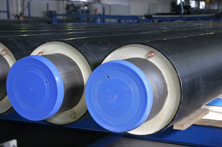
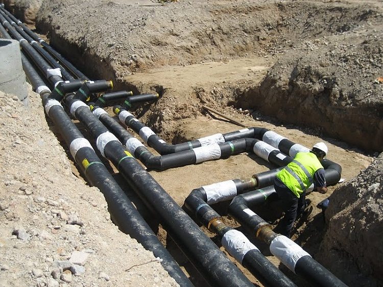
The TGI PPU pipe is a steel product, thermally insulated with a polyurethane foam layer and located in a waterproof sheath made of polyethylene (PE). Such channels are used to arrange heating networks underground. There are also products coated with galvanized steel (OC), represented by pipes TGI PPU OTs. The last type of channels is used for overhead installation.
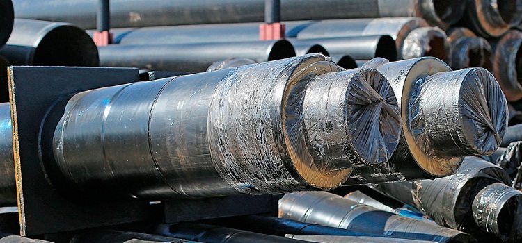
Thermally insulated pipes - this is the most acceptable material for the installation of underground networks
Content
The main features of pipes in OTs and PE
TGI pipes PPU PE and OTs include products made of steel, the characteristics of which comply with state standards 8731, 550, 8733, 10704, 20295 and 10705. The main parameters of the channels are given in GOST 30732. This normative document establishes the main dimensions of pipes without PE and OTs, which in the general case are 3.2-142.0 centimeters in diameter and up to 12 meters in length.
Note! Isolation of the joints of the channels is carried out by heat-shrinkable cuffs into which the components of the polyurethane foam are poured at the installation site.
All pipe products of this type are characterized by the presence of a moisture control system for the heat insulation layer — ODK, which allows you to quickly determine the damage points of PE / OC shells. GOST defines such coolant parameters: pressure not more than 1.6 MPa and temperature not more than 140 degrees, with a possible increase (short-term) to 150 degrees.
Non-insulated pipe ends can have a length of 150 mm with a deviation in the smaller direction of up to 20 mm for products with a diameter of PE / OTs shell up to 31.5 cm inclusive and 210 mm with the same permissible deviation for diameters of 40.0 cm or more.
Dimensions of products in accordance with GOST
Thermally insulated pipes in PE are divided into standard and reinforced - Type 1 and Type 2, respectively. The table shows the main dimensions of the channels and their shells.
Table 1
| The diameter of the steel pipe without shell and PPU, mm | Nominal value of the outer diameter (average) of products in PE | Nominal diameter of the OTs pipe, mm | |
| Type 1 cm | Type 2 mm | ||
| 32 | 12,5; 11,0; 9,0 | — | 125, 140, 100 |
| 38 | 12,5; 11,0 | — | 140, 125 |
| 45 | 12,5 | — | |
| 57 | 12,5 | 140 | 140 |
| 76 | 14,0 | 160 | 160 |
| 89 | 16,0 | 180 | 180 |
| 108 | 18,0 | 200 | 200 |
| 133 | 22,5 | 250 | 225 |
| 159 | 25,0 | 280 | 250 |
| 219 | 31,5 | 355 | 315 |
| 273 | 40,0 | 450 | 400 |
| 325 | 45,0 | 500 | 450 |
| 426 | 56,0 | 630; 600 | 560 |
| 530 | 71,0 | — | 710, 675 |
| 630 | 80,0 | — | 800, 775 |
| 720 | 90,0 | — | 900, 875 |
| 820 | 100,0 | 1100 | 1000, 975 |
| 920 | 110,0 | 1200 | 1100, 1075 |
| 1020 | 120,0 | — | 1200, 1175 |
| 1220 | 142,5 | — | 1400, 1375 |
| 1420 | 160,0 | — | 1600, 1575 |
The lengths of PE, spiral-walled shells made of thin-sheeted OC, and the heat-insulating layer should be equal. Possible tolerance: + 5.0 centimeters on each side of the product. The maximum deviations for the polyethylene sheath pipe are given in the table.
table 2
| The average outer diameter, cm | Wall, cm | ||
| Rated value | Maximum deviation upwards | Minimum value | Deviation (+) |
| 9,0 | 0,09 | 0,22 | 0,04 |
| 11,0 | 0,10 | 0,25 | 0,05 |
| 12,5 | 0,12 | 0,25 | |
| 14,0 | 0,13 | 0,30 | |
| 16,0 | 0,15 | 0,30 | |
| 18,0 | 0,17 | 0,30 | |
| 20,0 | 0,18 | 0,32 | |
| 22,5 | 0,21 | 0,35 | 0,06 |
| 25,0 | 0,23 | 0,39 | 0,07 |
| 28,0 | 0,26 | 0,44 | 0,07 |
| 31,5 | 0,29 | 0,49 | 0,07 |
| 35,5 | 0,32 | 0,56 | 0,08 |
| 40,0 | 0,36 | 0,56 | 0,09 |
| 45,0 | 0,41 | 0,56 | 0,11 |
| 50,0 | 0,45 | 0,62 | 0,12 |
| 56,0 | 0,50 | 0,70 | 0,13 |
| 63,0 | 0,57 | 0,79 | 0,15 |
| 71,0 | 0,64 | 0,89 | 0,17 |
| 80,0 | 0,72 | 1,00 | 0,19 |
| 90,0 | 0,81 | 1,12 | 0,22 |
| 100,0 | 0,90 | 1,24 | 0,24 |
| 110,0 | 0,99 | 1,38 | 0,27 |
| 120,0 | 1,08 | 1,49 | 0,29 |
| 142,5 | 1,26 | 1,73 | 0,34 |
| 160,0 | 1,44 | 1,96 | 0,39 |
Values of mass and deviations of the axial lines of the pipes
The calculated mass value of a running meter of a thermo-insulated pipe (GOST 30732) is given in the table.
Table 3
| Steel pipe | Mass g | |||
| Outer diameter cm | Wall mm | PE shell | Steel sheath | |
| Type 1 | Type 2 | |||
| 3,2 | 3 | 4080 | — | 6700 |
| 3,8 | 3 | 4500 | — | 7120 |
| 4,5 | 3 | 4980 | — | 7600 |
| 5,7 | 3 | 5790 | 6170 | 8410 |
| 7,6 | 3 | 7410 | 7960 | 10350 |
| 8,9 | 4 | 10810 | 11400 | 14160 |
| 10,8 | 4 | 13040 | 13790 | 16810 |
| 13,3 | 4 | 16950 | 18210 | 21370 |
| 15,9 | 4,5 | 22160 | 23860 | 26790 |
| 21,9 | 6 | 38970 | 41870 | 43950 |
| 27,3 | 7 | 58190 | 62590 | 63000 |
| 32,5 | 7 | 69610 | 74650 | 74160 |
| 42,6 | 7 | 94140 | 102790 | 97040 |
| 53,0 | 7 | 125900 | — | 121040 |
| 63,0 | 8 | 150220 | — | 143060 |
| 72,0 | 8 | 193320 | — | 181650 |
| 82,0 | 9 | 243330 | 266810 | 226070 |
| 92,0 | 10 | 278070 | 303890 | 253140 |
| 102,0 | 11 | 338590 | — | 304910 |
| 122,0 | 11 | 403340 | — | 363990 |
| 142,0 | 12 | 468100 | — | 423080 |
Deviations of the axial lines of the steel pipe and containment shells must not exceed the values given in the table.
Table 4
| The outer diameter of the shells, cm | Deviation of lines (axial), cm |
| Up to 16 incl. | 0,35 |
| St. 16 to 40 incl. | 0,50 |
| St. 40 to 63 incl. | 0,80 |
| St. 63 to 80 incl. | 1,00 |
| St. 80 to 120 incl. | 1,40 |
| St. 120 to 137.5 incl. | 1,60 |
| St. 135.5 to 160 incl. | 1,80 |
GOST also regulates the requirements for shaped elements.
Note! The thickness of the polyurethane foam layer of straight sections of shaped products and pipe insulation should be equal.
On the bends of the bends, deviations of the axial lines are permissible, which exceed the table values. The insulation thickness at any of the tap points should be at least 1.5 centimeters.
Requirements for joints of pipes and fittings
The standard establishes the requirements that must be met by thermal insulation of pipe joints made of steel and shaped elements:
- filling PPU into the joint space is recommended to be performed using filling machines, foam packs and other methods that ensure good mixing of the components of the polyurethane foam;
- shell joints, their connections with pipe shells must remain airtight during exposure to the internal space of the joint for 5 minutes with a pressure of 50 kPa;
- durability of joints not less than 30 years.
With channel-free piping, you can use start or axial bellows expansion joints (OSK). Thermal insulation of the latter is carried out by the manufacturer, and start-up - during installation of the network. The design of the OSK should ensure its tightness, which eliminates the ingress of moisture on the wire of the system (C) of the operational (O) remote (D) control (K) and in the thermal insulation.
Characteristics of PE pipe shells
The polyethylene sheath pipe should have a smooth outer surface.
Note! Acceptable are slight undulation and longitudinal stripes, which are included in the maximum deviations for the product wall.
The outer, end and inner surfaces are characterized by the absence of bubbles, shells, cracks, foreign inclusions, and the ends of the pipe-shells are burrs. The main parameters for such products are given in the table.
Table 5
| PE shell parameter | unit of measurement | Value |
| Elongation (relative) at break | % | Not less than 350 |
| The change in the length of the pipe-shell after heating at 110 degrees | % | No more than 3 |
| Resistance at a constant pressure and temperature of 80 degrees | h | Not less than 165 (if the initial stress in the tube wall is 4600 kPa) |
| Not less than 1000 (with an initial stress in the tube wall of 4 thousand kPa) | ||
| Resistance at a temperature of 80 degrees, a constant tensile load of 4 thousand kPa in an aqueous solution of surface-active substances | h | Not less than 2 thousand |
UEC for TGI products
Regulatory documents define the requirements and parameters of the insulating layer. The structure of PUF in the context is characterized by fineness, isolation and homogeneity. Voids larger than one third of the thickness of the polyurethane foam layer are not permissible. Under the cover shell of pipe insulation with a cross section of up to 42.6 centimeters inclusive, 2 indicator conductors made of soft copper (MM, 1.5 mm) are installed2), for the UEC system. Their distance to the steel product is 2.0 ± 0.2 cm. When the longitudinal seam of the pipe is upper, the conductors should be located at points corresponding to 9 and 3 hours.
For products with a cross section of 53.0 cm and more, 3 conductors are installed in positions 3, 12 and 9 hours. The position of the longitudinal weld of a steel pipe is 12 ± 2 hours. The value of electrical resistance between the steel channel and the connected copper conductors, the steel sheath and the connected indicators is not less than 100 thousand kOhms with a test voltage of not less than 500 V.
Heat-insulated steel pipes (with PE or OTs) are characterized by a long service life, resistance to external influences, and also allow the overhead or underground installation of heating networks to be completed in a short time.
