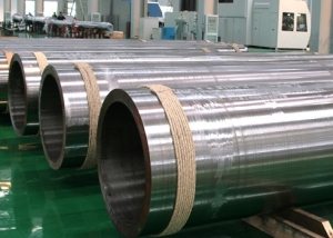
Regulatory documents, standards for pipes among other characteristics highlight the "moment" and "radius" of inertia. These values are important when solving problems of determining stresses in products with specified geometric parameters or when choosing the best resistance to torsion or bending. The moment and inertia radius of round pipes are also used to calculate the structural strength.

The stability of steel pipe structures depends on how correctly calculated strength indicators of pipe products
Content
- 1 The essence of the theory of strength
- 2 Types of structural deformation
- 3 Elements of the theory of tube torsion
- 4 The concept of moment of inertia of a round pipe
- 5 The concept of the radius of inertia of the pipe
- 6 Calculation formulas for some simple shapes
- 7 Features of deflection of products
- 8 Pipeline Strength Test Standard
The essence of the theory of strength
Strength theories are used to assess the resistance of structures when exposed to volumetric or plane stresses. These tasks are highly complex, since in the case of a biaxial, triaxial stress state, the relations between tangent and normal stresses are very diverse.
The mathematical description of the influence system — the stress tensor — contains 9 components, 6 of which are independent. The task can be simplified by considering not six, but three main stresses. In this case, it is necessary to find such a combination of them that would be equally dangerous to simple compression or extension, i.e., to a linear stress state.
The essence of theories (criteria, hypotheses) of strength is based on determining the predominant influence of a particular factor and selecting the appropriate equivalent stress, and then comparing it with simpler uniaxial tension.
Among the causes of the onset of a dangerous condition are:
- normal stresses;
- linear deformations;
- shear stresses;
- strain energy, etc.
The appearance of large residual deformations for ductile materials and cracks - for brittle ones lies on the boundary of the region of elastic deformation. This makes it possible to use formulas in the calculations that are derived under the conditions of applicability of Hooke's law.
Types of structural deformation
Often pipes of various cross-sectional shapes (square or round) are the basis of various designs. However, they can be subjected to one of these possible effects:
- stretching;
- compression
- shear;
- bend;
- torsion.
Regardless of the material of execution, pipes by their nature are not absolutely rigid products and can be deformed under the influence of external forces (i.e., to some extent change their dimensions and shape). At some point, structural points may change position in space.
Note! The rate of change in size can be described using linear deformations, and shape - shear deformations.
After unloading, deformations can either completely or partially disappear. In the first case, they are called elastic, in the second - plastic or residual. The property of the pipe after unloading to take its original shape is called elasticity. If deformations at all points and conditions of fastening of the products are known, then it is possible to determine the movements of absolutely all structural elements.
Normal operation of structures suggests that the deformations of its individual parts must be elastic, and the displacements that they cause must not exceed acceptable values. Such requirements expressed by mathematical equations are called stiffness conditions.
Elements of the theory of tube torsion
The theory of torsion of a circular pipe is based on the following assumptions:
- cross-sections of the product do not cause other stresses other than tangent;
- when turning the cross sections, the radius does not bend, remaining flat.
When twisting, the right section will undergo rotation relative to the left by an angle dφ. In this case, the infinitesimal element of the pipe mnpq will shift by the value nn´ / mn.
Omitting the intermediate calculations, we can obtain a formula by which the torque is determined:
Mk = GθIp,
where G is the weight; θ is the relative twist angle equal to dφ / dz; Ip is the moment of inertia (polar).
Assume that the pipe section characterizes the outer (r1) and inner (r2) radius and the value α = r2 / r1. Then the moment (polar) of inertia can be determined by the formula:
Ip = (π r14/32)(1- α4).
If the calculations are carried out for a thin-walled pipe (when α≥0.9), then an approximate formula can be used:
Ip≈0.25π rav4t
where rav is the average radius.
The shear stresses arising in the cross section are distributed along the radius of the pipe according to a linear law. Their maximum values correspond to the points that are farthest from the axis. For an annular cross section, the polar moment of resistance can also be determined:
Wp≈0.2r13(1-α4).
The concept of moment of inertia of a round pipe
The moment of inertia is one of the characteristics of the distribution of body mass equal to the sum of the products of the squares of the distances of the points of the body from a given axis by their masses. This value is always positive and not equal to zero. The axial moment of inertia plays an important role in the rotational motion of the body and directly depends on the distribution of its mass relative to the selected axis of rotation.
The more mass the pipe has and the farther it is from some imaginary axis of rotation, the greater the moment of inertia belongs to it. The value of this quantity depends on the shape, mass, dimensions of the pipe, as well as the position of the axis of rotation.
The parameter is important when calculating the bending of a product when it is affected by an external load. The relationship between the magnitude of the deflection and the moment of inertia is inversely proportional. The larger the value of this parameter, the smaller the deflection will be and vice versa.
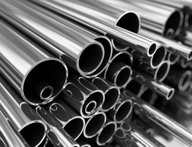
When calculating, it is important to consider pipe parameters such as diameter, wall thickness and weight
The concept of the moment of inertia of the body and a flat figure should not be confused. The last parameter is equal to the sum of the products of the squared distances from the flat points to the axis under consideration on their area.
The concept of the radius of inertia of the pipe
In general, the radius of inertia of a body about an axis x Is that distance iwhose square, when multiplied by the mass of the body, is equal to its moment of inertia about the same axis. That is, the expression is fair
Ix= m i2.
For example, for a cylinder relative to its longitudinal axis, the radius of inertia is R√2 / 2, for a ball relative to any axis - R√2 / √5.
Note! In the resistance to longitudinal bending of pipes, the main role is played by its flexibility, and, consequently, the smallest value of the radius of inertia of the section.
The value of the radius is geometrically equal to the distance from the axis to the point at which it is necessary to concentrate the entire mass of the body so that the moment of inertia at this one point is equal to the moment of inertia of the body. Also distinguish the concept of the radius of inertia of the section - its geometric characteristic, which connects the moment of inertia and the area.
Calculation formulas for some simple shapes
Different cross-sectional shapes of products have different moment and radius of inertia. The corresponding values are given in the table (x and y are the horizontal and vertical axes, respectively).
Table 1
| Sectional shape | Moment of inertia | Radius of inertia |
| Annular (r1 - outer diameter, r2 - inner diameter, α = r1 / r2) | Jx= Jat= πr24(1-α4)/64
or Jx= Jat≈0.05 r24(1- α4) |
ix= iat= r2√ (r12+ r22)/4 |
| Thin-walled square (b - side of the square, t - wall thickness, t≤ b / 15) | Jx= Jat= 2b3t / 3 | ix= iat= t / √6 = 0.408t |
| Hollow square (b is the side of the square, b1 is the side of the internal cavity of the square) | Jx= Jat= (b4-b14)/12 | ix= iat= 0.289√ (b2+ b12) |
| A hollow rectangle, the x axis is parallel to the smaller side (a is the larger side of the rectangle, b is the smaller side, a1 is the larger side of the inner cavity of the rectangle, b1 is the smaller side of the inner cavity) | Jx= (ba3-b1a13)/12
Jat= (ab3-a1b13)/12 |
ix= √ ((ab3-a1b13) / (12 (ba-a1b1))
iat= √ ((ba3-b1a13) / (12 (ba-a1b1)) |
| Thin-walled rectangle, the x axis is parallel to the smaller side (t is the wall thickness of the figure, h is the larger side, b is the smaller side) | Jx= th3(3b / h + 1) / 6
Jat= tb3(3h / b + 1) / 6 |
ix= 0.289h√ ((3b / h + 1) / (b / h + 1))
iat= 0.289b√ ((3h / b + 1) / (h / b + 1)) |
Features of deflection of products
Bending is a type of loading during which bending moments appear in the cross sections of the pipe (rod). These types of bending are distinguished:
- clean;
- transverse.
The first type of bending occurs when the only force factor is the bending moment, the second when the transverse force appears together with the bending moment. When the loads are in any plane of symmetry, then under such conditions the pipe experiences a straight flat bend. During bending, the fibers, which are located on the convex side, undergo tension, and with the concave side, under compression. There is also some layer of fibers that do not change the original length. They are in the neutral layer.
Note! The points that are farthest from the neutral axis are subject to the greatest tensile or compressive stress.
If the fiber is spaced at from a neutral layer with a radius of curvature μ, then its relative elongation is equal to у / μ. Using Hooke's law and omitting all the intermediate calculations, we obtain the expression for the voltage:
σ = yMx/ Ix,
where Mx - bending moment, Ix Is the moment of inertia associated with ix (radius of inertia of the pipe (square, round)) by the ratio ix= √ (Ix/ A), A is the area.
Pipeline Strength Test Standard
Regulatory documents define methods for calculating pipelines for vibration, seismic effects and strength. For example, GOST 32388 from 2013 extends its effect to technological pipelines that operate under pressure, external pressure or vacuum and made of alloyed, carbon steel, copper, titanium, aluminum and their alloys.
The standard also applies to pipes made of polymers with temperatures up to one hundred degrees and pressure (working) up to 1 thousand kPa, which transport gaseous and liquid substances.
The document defines the requirements for finding the wall thickness of pipes under the influence of excessive internal and external pressure. In addition, methods for calculating the stability and strength of such pipelines are established. GOST is intended for those specialists who carry out the construction, design or reconstruction of technological highways of gas, oil refining, chemical, petrochemical and other related industries.
Durability and pipe stability are important indicators of product quality and durability. Calculations of the parameters defining such characteristics are cumbersome and complex.
